microcontrollers
Raspberry PI and Arduino Tutorials
| KBS - Home |
|---|
| microcontrollers |
| LED |
| Button |
| RPI Camera |
| LCD Display (16x2) |
| LED Matrix (8x8) |
| 7-segment Display |
| RFID RC522 |
LCD Display
16x2 LCD Display
The LCD display has the following pins:
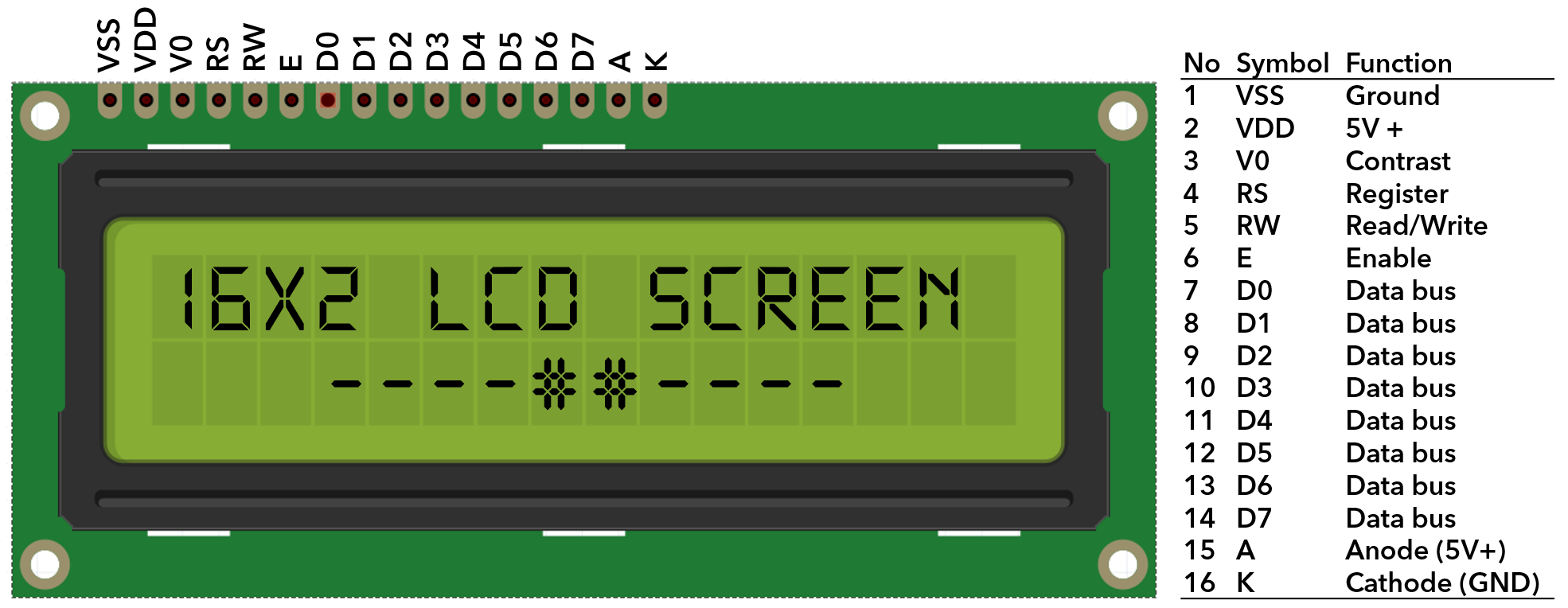
The pin names can be different but the pin order should be the same.
Connections
Here connections between a 16x2 LCD display, a 10K potentiometer, a Raspberry PI 3 B+ and a bread board is provided. Alternatively the display can be directly connected to the PI by connecting all power and ground pins (1, 2, 5, 15 and 16) on the LCD to power and ground pins on PI.
Potentiometer
A 3 pin 10 K potentiometer can be used to adust contrast of the LCd display. When faced to the shaft, left pin goes to 5V positive, right pin goes to 5V negative in bread board and middle pin goes to V0 pin of the LCD.
| No | LCD | GPIO | Pin | Bread Board | Potentiometer |
|---|---|---|---|---|---|
| 1 | VSS | 5V- | Right (-> BB) | ||
| 2 | VDD | 5V+ | Left (-> BB) | ||
| 3 | V0 | Middle (-> LCD) | |||
| 4 | RS | 25 | 22 | ||
| 5 | RW | 5V- | |||
| 6 | E | 24 | 18 | ||
| 7 | D0 | ||||
| 8 | D1 | ||||
| 9 | D2 | ||||
| 10 | D3 | ||||
| 11 | D4 | 23 | 16 | ||
| 12 | D5 | 17 | 11 | ||
| 13 | D6 | 18 | 12 | ||
| 14 | D7 | 22 | 15 | ||
| 15 | A | 5V+ | |||
| 16 | K | 5V- |
Python
There are two main LCD libraries for Raspberry PI:
Time
Here is an example of time display using Adafruit library:
import Adafruit_CharLCD as LCD
from time import sleep, strftime
from datetime import datetime

# Raspberry Pi pin configuration:
lcd_rs        = 25
lcd_en        = 24
lcd_d4        = 23
lcd_d5        = 17
lcd_d6        = 18
lcd_d7        = 22
lcd_backlight = 4

lcd_columns = 16
lcd_rows    = 2

# Initialize the LCD using the pins above.
lcd = LCD.Adafruit_CharLCD(lcd_rs, lcd_en, lcd_d4, lcd_d5, lcd_d6,
                           lcd_d7, lcd_columns, lcd_rows, lcd_backlight)

while 1:
    lcd.message(datetime.now().strftime('\n%b %d  %H:%M:%S\n'))
    sleep(1)
External Links
- Time python code
- Wiring Ada Fruit
- Wiring 2
- Wiring video
- [LCD-figure]: